Pool Control Project
Published at 8/14/2020
Project Pool PI
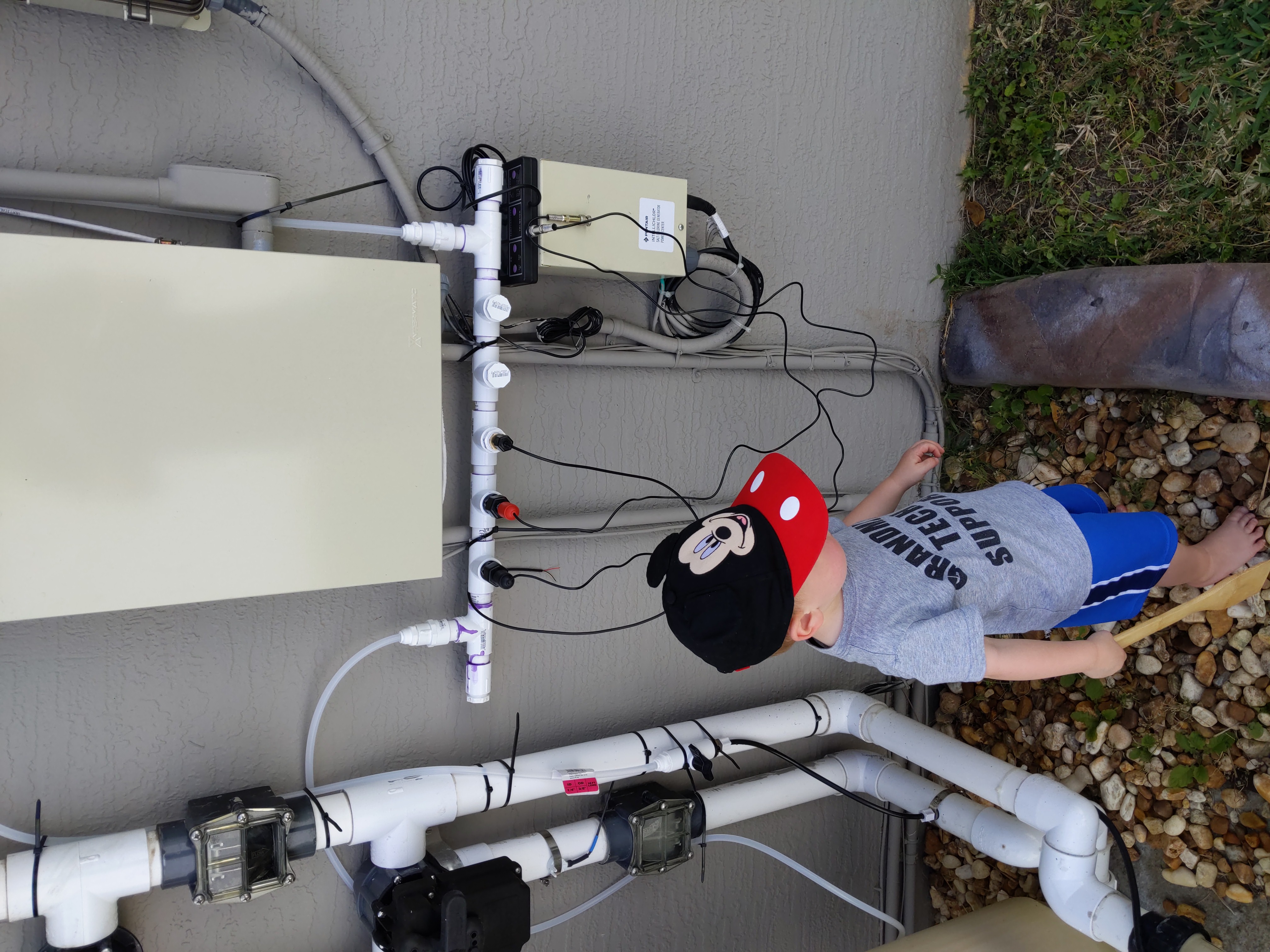
This project is my self hosted pool controller. When we moved into our house in Florida, I had no idea about running a swimming pool, pool maintenance or any thing of the sort. The pool at our new house was pretty standard, with a salt chlorinator, some fountains, a big pool filter, and solar hot water heater panels. It had a remote for the pool light and pump, and needed at least weekly checks for ph and chlorine. My wife would always ask what the water temperature was, and if we should be using the solar heaters, which needed a valve switched and the pump turned on to use. I figured it wouldn’t take too much to setup an automated system.
Pool Monitor
The initial part of this project was to find a way to leverage Home Assistant, which I was already running at my house, to show the pool information so that my wife could see the pool information. I set up MQTT, and made a small JavaScript program to run on a Raspberry PI Zero outside at the pool control panel. This program initially used a BME680 to get outside air temperature and humidity, and a DS18B20 one wire temperature sensor in a stainless steel tube to measure the pool water temperature. Eventually I made a bypass pipe that took a sample of pool water from the pressure side after the pump, ran it past the temperature sensor, an Atlas Scientific Ph sensor and ORP sensor, and along with a water pressure sensor so that the system knew when the pump was running. These values were all sent over the network to the MQTT server, and then displayed and logged by Home Assistant.
Pool Valve Controller
The pool valves installed changed the path of the water after the pump, which controlled the water fall, shallow end fountains, and the solar hot water panels. The available pool valve motors to move these valves used 24 Volts AC, and would move all the way to an end stop then turn off with safety switches. If the power was sent to the other terminal, it would run all the way to the other stop and turn itself off. My problem with this is that my fountains and waterfall were on one valve, and if I wanted to run both, then the valve had to be placed into a middle position, and if I wanted gentle fountains and no water fall, then an upstream valve needed to be placed into an intermediate position, and the waterfall/fountain valve set to one side.
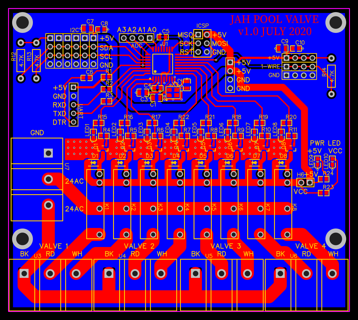
My solution wast to make a control board, with a set of relays so that the control board could not only choose the terminal to run power to, but for how long. By measuring the time it took to run the valve from one side to the other, I could first run in one direction for an extended amount of time to guarantee that the valve was in a know starting location, then move the other way for a computed amount of time, and when the controller turned the power off, the valve would be stopped in a set middle position. Using a Home Assistant slider control, you could pick the position you wanted, and the system would move the valve to the correct position.
Pool Chemical Control
Unfortunately, we moved to Kansas before this part of the project was implemented, but the plan was to use Pentair acid and chlorine dosing tanks, which use a small pump to dose the pool on a continuous basis and use the measured Ph and ORP (chlorine) levels to keep the chlorine and Ph at set values using a closed feedback loop and PID control to prevent overshoots. Two of the relays on the pool valve control board would be used to run these pumps, and the run time per day was going to be used in the PID loop to keep the values steady. While the salt chlorinator was still working, only the acid pump would be used for Ph control, and the power to the salt chlorinator would be turned on and off as needed to meet the chlorine level.
Programming
The code for monitoring the sensors and controlling the outputs was made in JavaScript, to run on Nodejs on a PI Zero outside at the pool. The PI Zero was connected to the output pool control boards with I2C. The control boards used C++ (arduino) for their firmware. This software is available at my github at jahartley/poolController
Pool Valve Circuit Boards
I designed the circuit schematics, laid out the PCB traces and had them manufactured by JLCPCB. 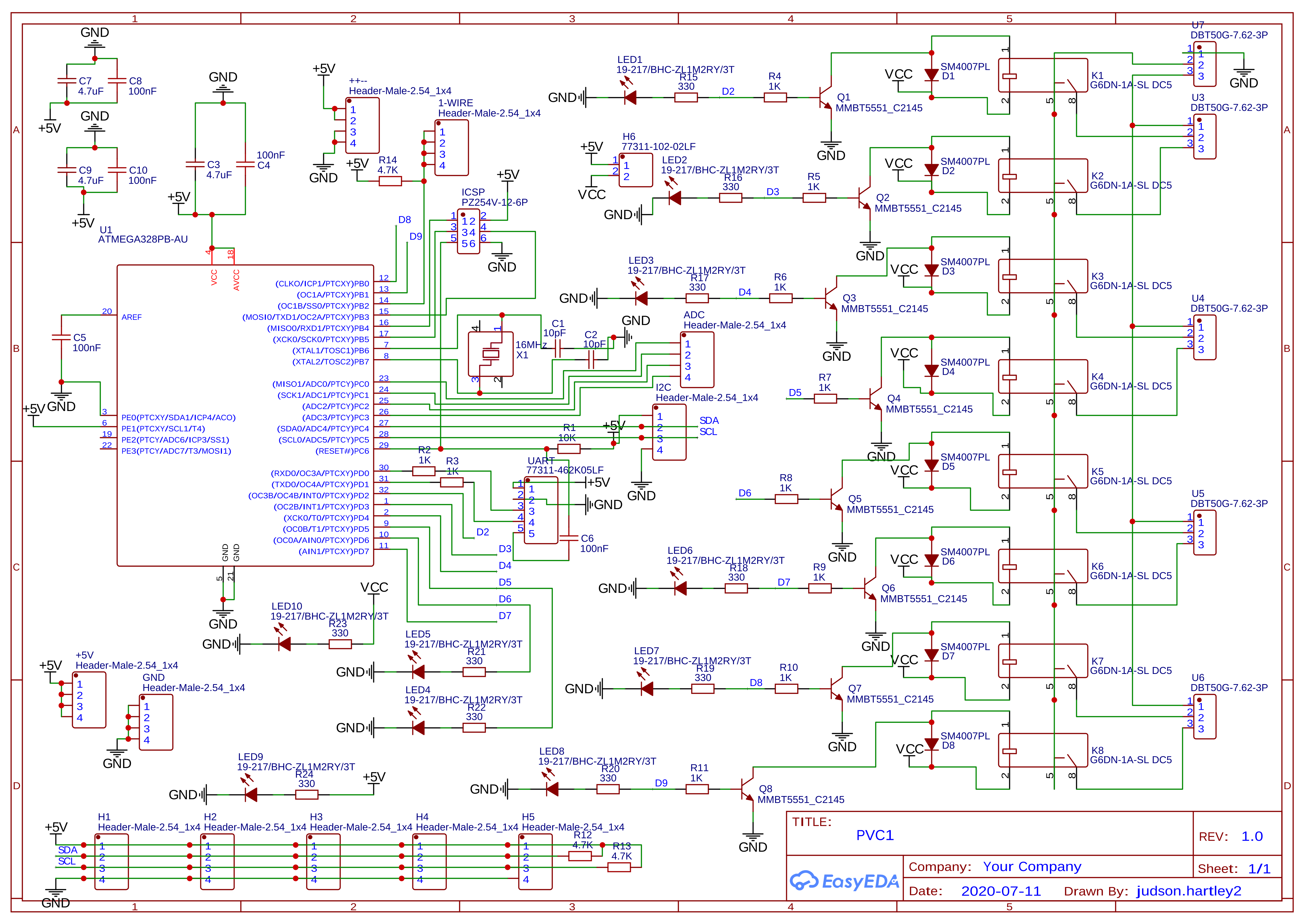
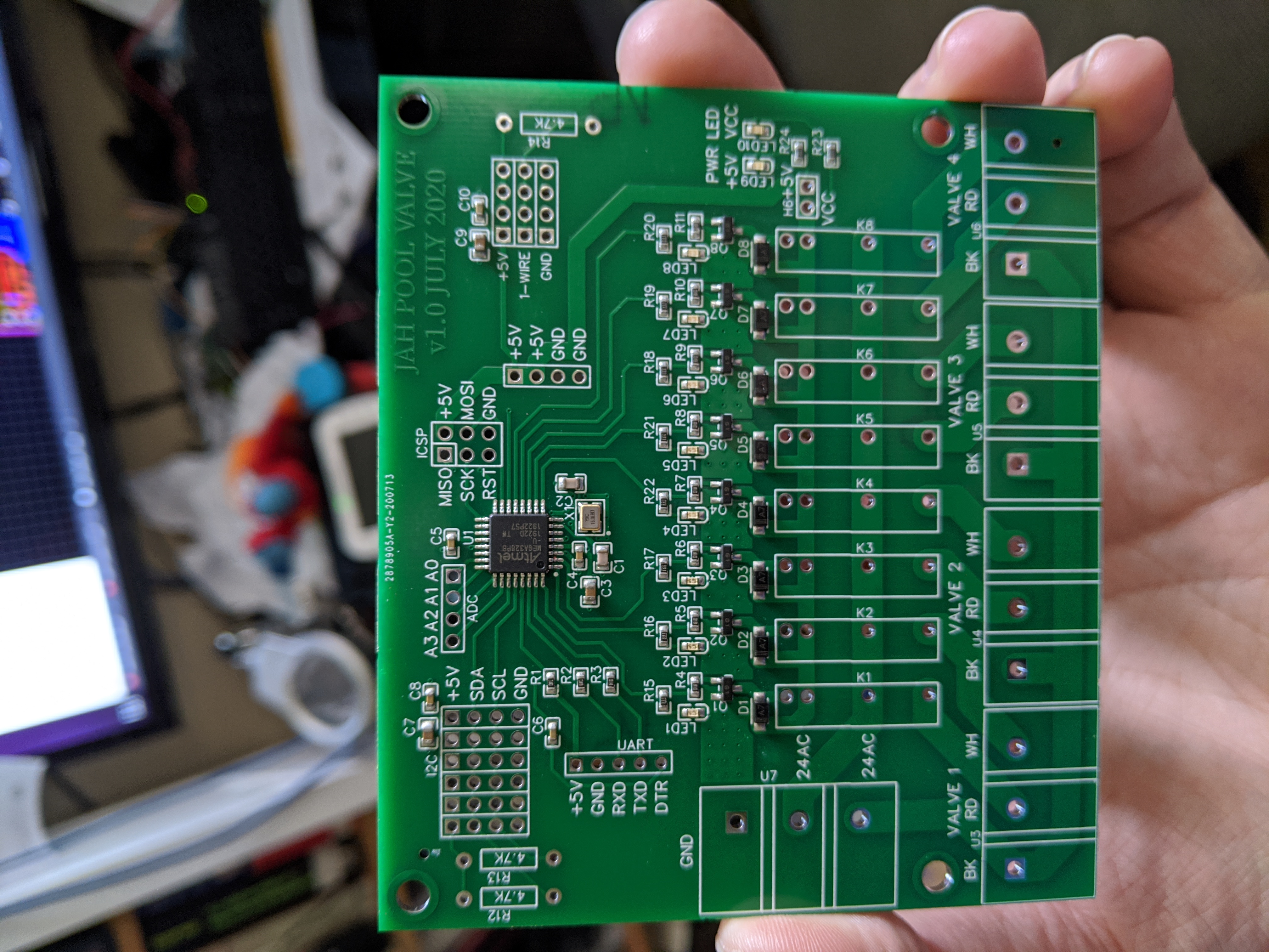
When I got the boards, I finished soldering on the through hole components, then flashed the firmware, and tested the boards.
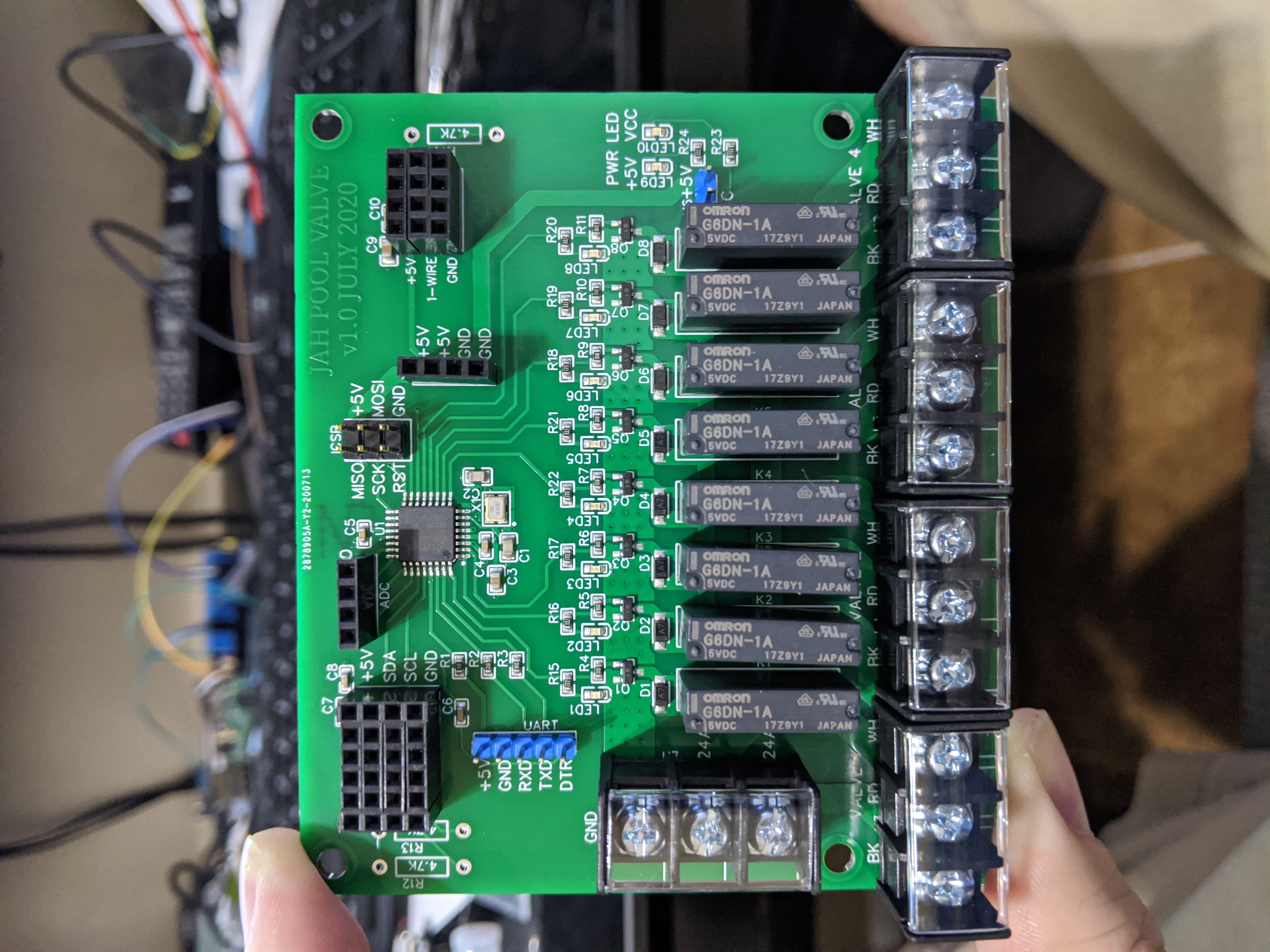
The pool valve controller board connects to the PI using I2C, and the PI gets and sends messages to Home Assistant over MQTT. I ran a Cat 5 cable from my office to the pool panel, and all the hardware is powered by power over ethernet.
This project provided us easily accessible pool information and valve control right from the Home Assistant application on our cell phones, and I didn’t have to do another pool water test for the rest of the time we lived there.